Custom Bicycle Light - Mechanical
The design process started with the housing and trying to make an elegant form that was user-friendly and struck a balance between being small and lightweight while also being large enough to fit all the electrical components that would ensure a decent battery life. The final case features a pill-shaped design with a slotted opening for 8 LEDs and angled ridge to create room for both an 1800mAh lithium-ion battery and single push button switch.
Because the LEDs needed to be recessed within the case for waterproofing, a decent amount of the usable light from LEDs went into the case and did not contribute to the effective brightness of the product. Therefore, a light reflector was designed to reflect light toward the opening and increase the angle of visibility of the light from the side. This reflector is positioned on top of the main PCB board with openings for the LEDs. A clear bevelled screen was also designed to sit on top of the reflector to water seal the light opening and prevent damage to the electronics.
The male component of a common GARMIN bicycle mounting system was designed to fit on the bottom half of the enclosure and be permanently glued. It needed to be a separate piece to make the bottom half manufacturable by 3D printing and injection molding. The mounting system was chosen to make it easy to use with products already commercially available.


A single push button was chosen for this design to create a simple interface for the user that could be easily used while in the middle of riding. More complicated functions that would likely not need to be performed while riding were accomplished via a Bluetooth connection to the Nordic microcontroller on the light board. However, because the button needed to be big enough and have tangible travel distance to allow for intuitive use, an assembly was designed to waterproof the push-button opening in the top of the case. The button assembly includes 3 parts: the button cap, a partially slotted mount, and an O-ring. The design allows for assembly of the push-button before being inserted into the case by twisting the cap into the mount, but it locks the button cap and prevents any disassembly after the light casing is glued together.
Injection Points

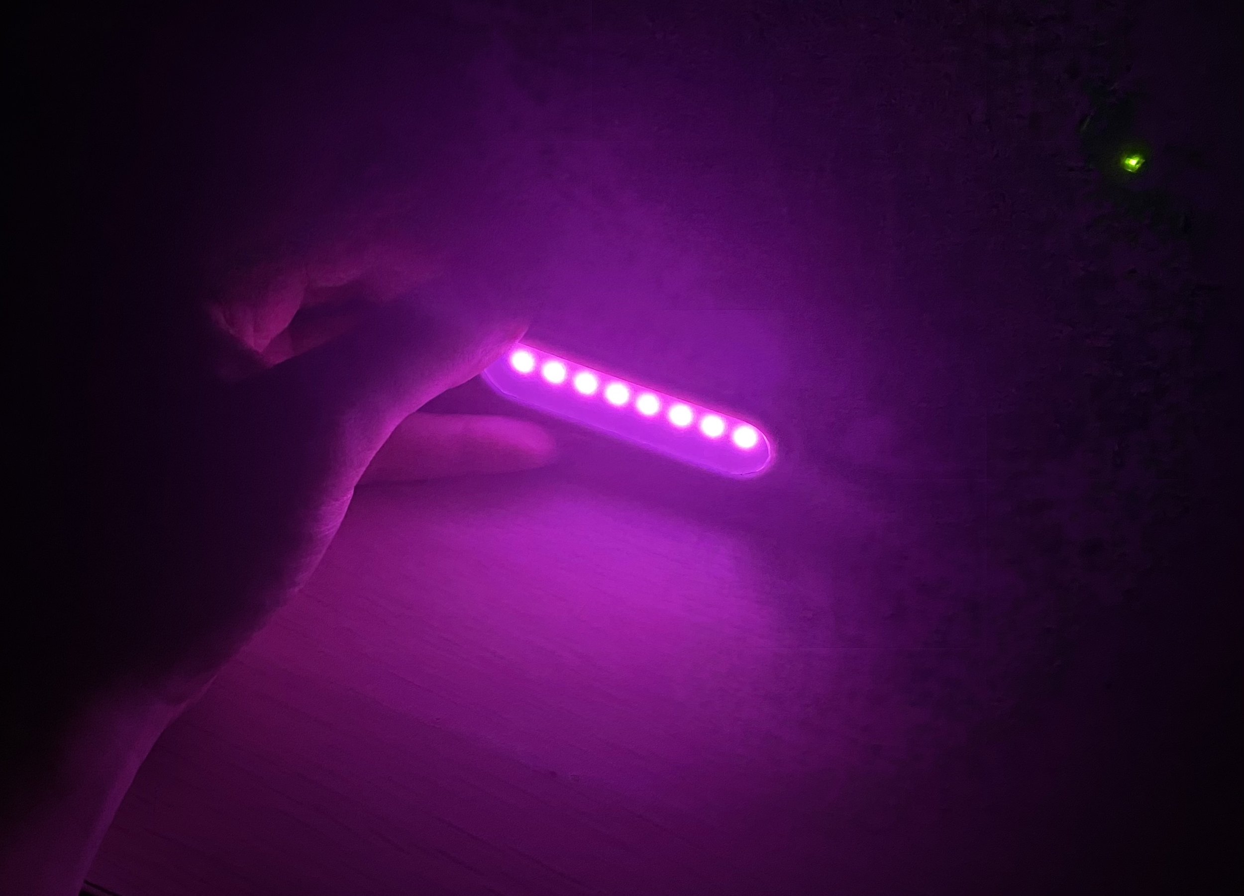
A full prototype of the assembly was manufactured using a Formlabs Form 3 resin 3D printer. This method was chosen over an FDM 3D printer to achieve the design surface finish and tolerance between assembled pieces. The material also resembles the properties of an injection molded plastic. Part of the prototype reflector broke at the LED openings. However, all of the pieces were able to be assembled and once the electronics and software were set up, the light was successfully installed and used on a bicycle.
To validate the large-scale production of this design of enclosure, injection molded manufacturing simulations were performed on both halves of the enclosure and the light reflector. The exposed outer surfaces of these pieces were selected as “aesthetic surfaces” that should appear smooth. The inner surface, that would not be seen when the part is assembled would have injection and ejector pin marks. The number and positioning of injection points were adjusted until the deflection and shrinkage were reduced.
The mechanical portion of the project involved designing a water-proof case that housed all of the electronics, maximized light output and visibility, allowed for user input, charging, and easy mounting to a bicycle. Prototypes were resin 3D printed and assembled with the electronics. The geometry was validated for large-scale manufacturing with injection molding simulations.


Flow-front Temperature

QualityVolumetric ShrinkageThe case needed to be split into two separate pieces along the ridge for manufacturing and assembly purposes to create a design that could be plastic injection molded or easily 3D printed. During assembly, the battery, USB charging/programming port, and push-button are assembled in the bottom half while the LED board, reflector, and a clear protection screen are assembled in the top half, after which both halves are permanently glued together.

Deflection


Injection Pressure