Electric Bicycle - Motor & Frame

The general design goals for the bicycle are to support a combined weight of up to 300 lbs, have an electrical assist range of at least 20 miles, a max speed of at least 28 mph with and without the motor, weigh less than 40 lbs, and be easily maneuverable. From these specifications, the motor was specified to provide roughly 500W of power, operating at 48V with a rated current of 10A. To provide the necessary torque for the desired speed and the confined geometry of a bicycle wheel, a planetary gear system with a 5:1 ratio is used to increase to the torque output of the motor.
Siemenns Motorsolve was used to design and simulate stator and rotor configurations that produce the specified torque and speed. The final design is an outrunner 3-phase, 18-slot, and 20-pole brushless DC motor. Additional mechanical simulations were performed with ANSYS mechanical to verify the structural integrity of the motor, hub shell, and axle.


The next part to make for the motor was the rotor, which is the spinning component that holds pairs of opposing polarity permanent magnets. While the steel back-iron was being machined, a plastic version was 3D-printed and tested with the finished stator. It was also safer to run the motor for the first time with a lightweight plastic component spinning at a couple thousand RPM instead of a much heavier steel piece.
This plastic rotor spun at over 6000 rpm with only 30V and 3A input voltage and current, less than 1/5 of the expected maximum input power. While not having to carry the load of a bicycle and rider, this rotational velocity corresponds to a wheel speed of over 100 mph.

After the steel rotor was assembled and testing was repeated, the entire hub was assembled and the spokes were laced to the wheel rim. With 36 spokes, the lacing pattern uses 2 spoke crossings to provide rigidity to the wheel without making it difficult to assemble. Once laced, a test was performed with the fully assembled rear wheel. With the added inertia of the steel rotor, spokes, rim, and tire, the wheel spun at over 600 rpm with only 90W of input power. This corresponds to over 50 mph of ground speed.

Full drawings for the motor and rear wheel assembly can be found here.
For ME310, our class designed and manufactured an urban commuter bike for NYC during the 2022-2023 school year. I was a member of the powertrain team, which was responsible for both the drivetrain mechanism that transfers power from the pedals to the rear wheel and the hub motor inside of the rear wheel. Specifically, myself and another teammate focused on designing and manufacturing the hub motor installed on the rear wheel of the bicycle that will provide mechanical power to assist the rider. Successful implementation of the hub motor for this project will provide insight for the school FSAE team for potentially manufacturing hub motors for the race car in future years. Additionally, I helped design portions of the bicycle frame that interface with the entire powertrain system and assisted the machinist notch the frame tubes for welding.
The general design goals for the bicycle are to support a combined weight of up to 300 lb, have an electrical assist range of at least 20 miles, a max speed of at least 28 mph with and without the motor, weigh less than 40 lbs, and be easily maneuverable. From these specifications, the motor was specified to provide roughly 500W of power, operating at 48V with a rated current of 10A. To provide the necessary torque for the desired speed and the confined geometry of a bicycle wheel, a planetary gear system with a 5:1 ratio is used to increase to the torque output of the motor.


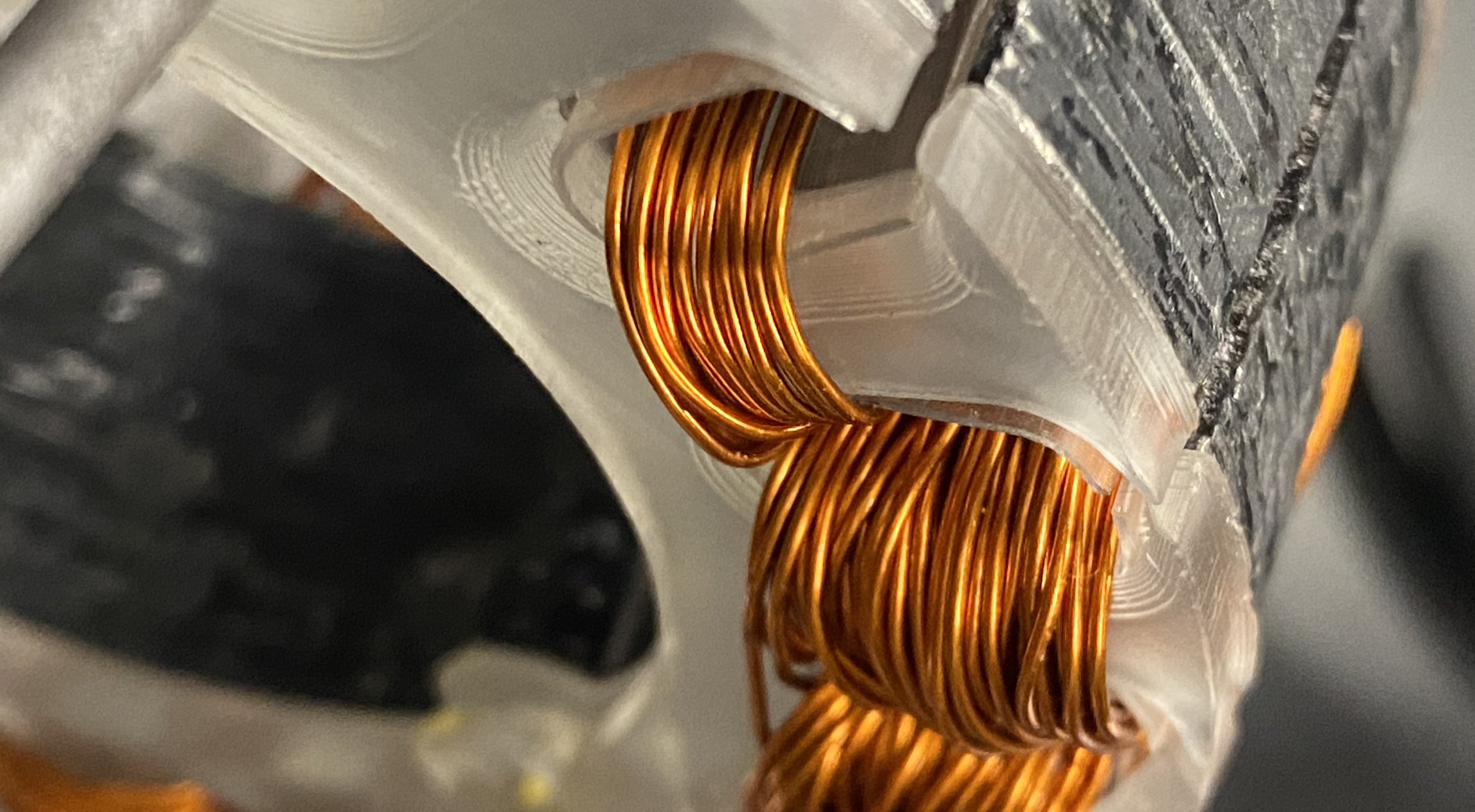
Easily the hardest part of the manufacturing and assembly process was making the motor stator. This involved both laminating 48 pieces of steel together to make the stator core and also winding the phase coils around the stator teeth. The stator laminations were laser cut from 0.02” thick low-carbon steel and then epoxied together with potting epoxy with 3 alignment bolts. After removing excess carbon, the 3 phase wires were wrapped around each tooth. Each coil consisted of 8 turns of 6 parallel strands of 24 ga. insulated copper wire. To prevent the enamel insulation from wearing away and causing the phases to short to the metal stator core, a plastic over-mold was 3D printed to insulate the stator.
To provide the necessary torque for the desired speed and the confined geometry of a bicycle wheel, a planetary gear system with a 4.4:1 ratio is used to increase to the torque output of the motor. The planetary gears used to accomplish this speed reduction make up most of the components that were not made in-house because of the complexity and time-constraints of the project.
The ring gear is attached to the center piece of the hub shell with flanges for spoke holes. Three planetary gears on a clutched carrier transfer torque from the sun gear, which is attached to the motor rotor. The carrier has a clutch to prevent electrical resistance while the motor is not powered and the rider is pedaling. The hub shell center rotates around the axle independently of the motor using two side mounting plates. One of the plates is used to mount the rear sprocket and the other is used to mount a disc brake rotor.
After the frame tubes were notched and welded together. The fully assembled bike successfully completed a trip on city streets. Next steps involve adding sensors for an e-assist controller, rear-brake caliper mounting, and sealing the frame with paint.