Hydrostatic Vacuum Tube
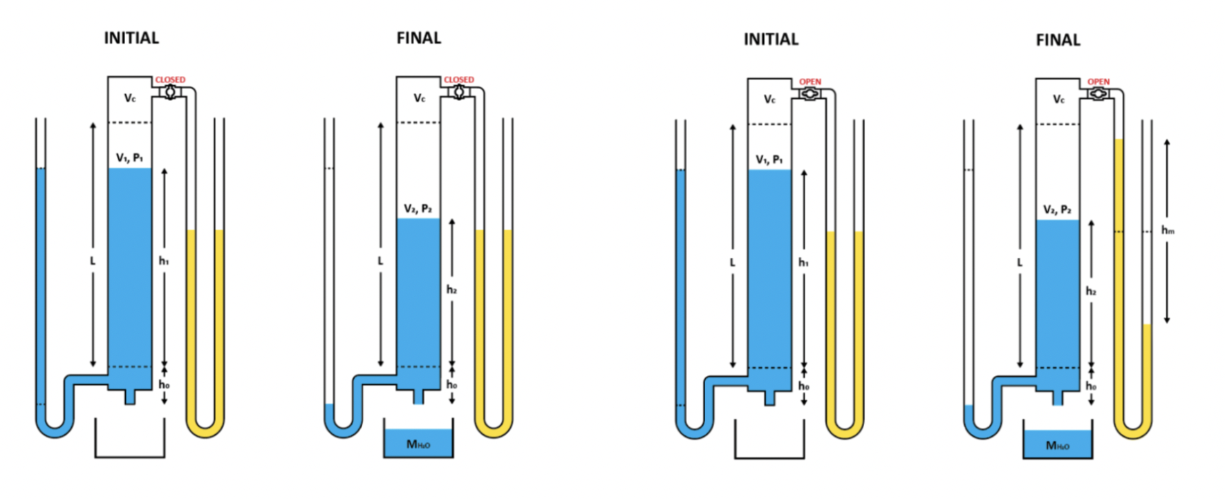
Because our testing apparatus had a "dead volume" at the top that contained air at sea-level pressure, a certain amount of water had to be drained to expand the air in this volume and create a vacuum large enough to hold the remaining water. One of the experiments we conducted tested the total volume of water drained for different initial volumes. Experimentally collected values were compared to different models that predicted the draining volume using Bernoulli's equation and the combined gas law. With the exception of one outlier, all of the data is consistent with the expected theoretical values.

Since the vacuum pressure of the air contained at the top of the tube is proportional to the volume of water remaining in the tube, the expected vacuum pressure was compared to pressure values obtained with a manometer and two pressure transducers. Different vacuum pressure measurements were used to calibrate the pressure transducers and verify the manufacturer's specifications of the sensor planned for future use within the school's building management system.
One of the pressure transducers was connected to an Arduino to collect pressure measurements in order to analyze the transient pressure of the air at the top of the tube to its final vacuum pressure. These values were compared to the pressure indicated by the fluid in a manometer, which was captured on a slow-motion video. The second order effects of the inertia of the water in the manometer can be seen causing oscilliations in comparison to the much lighter medium of air which is measured by the pressure transducer.
The bottom of the HVT tube was connected to various PVC joints and values to perform different steps in the experiment. Two valves were used to drain the water in the HVT tube and generate a vacuum, one valve small enough to maintain surface tension and another larger valve that allowed air bubbles to enter the outlet and water to flow. Another valve was used to attach a pump to fill the tube with water. A barbed outlet was used to connect to a flexible tube that served as a manometer for measuring the water pressure at the drain.

A PVC tube assembly was used to connect to the union joint at the top of the HVT to measure the vacuum presure. Two ports were used to connect to the two pressure transducers. An additional valve was used to release and seal the vacuum pressure in the top of the HVT. While this added pipe increased the dead-volume in the HVT, it was necessary to keep the sensors at eye-level and easily readable.

To accurately calculate the vacuum pressure in the HVT, it was important to account for the exact amount of “dead-volume” in the top of the tube. The difference between the theoretical curves when this static dead-volume is and is not accounted for becomes dramatic for larger initial volumes of water. However, when the sensor-valve at the top assembly of the HVT is opened, there is additional dead-volume added to the tube. Furthermore, the manometers add a loading-error to the dead-volume, because as the vacuum pressure increases, the dead-volume decreases because water is “sucked” into the top of the tube to create a height differential in the water to indicate the negative pressure. Once this loading-error was accounted for, the experimentally collected values with the sensor valve opened was consistent with the expected theoretical curve.
A transient pressure test was also conducted when a different draining orifice was used. This orifice was large enough to prevent the fluid from keeping surface tension and it allowed bubbles to enter into the tube. Since the bubbles were at atmospheric pressure, when they rose to the tube, the vacuum pressure decreased and water drained from the tube. Again, the manometer pressure readings taken from slow motion video show oscillations in comparison to the pressure transducer.
The final report and a complementary report published in the IMECE 2023 conference are contained below with more details of the experimental setup and results.
For ME-360 (Experimentation), I was part of a group of students working on a hydrostatic vacuum tube (HVT) to collect static and transient pressure measurements and verify the specifications of an electronic pressure sensor for potential use within the HVAC system of the school building. The vacuum tube operates with the same principles as a straw full of liquid with its top covered; the liquid inside does not fall out because of an air vacuum at the top of the tube. To prevent the liquid from draining out of the bottom, the orifice needs to be small enough to maintain surface tension and the top needs to be sealed air tight.

At the top of the clear HVT are various PVC joints and valves to seal and measure air pressure. There was “dead volume” where water could not be filled to the top of the tube without leaking into the manometer and transducer pipes. This was mainly contained at the top of the tube (in green). A brass valve was used to open and close the top to ambient pressure. A barbed port was used to connect to a flexible tube that served as a manometer to measure the vacuum pressure. A union joint was used to connect to a PVC assembly for different pressure transducers.
