
Autonomous Path Following Vehicle
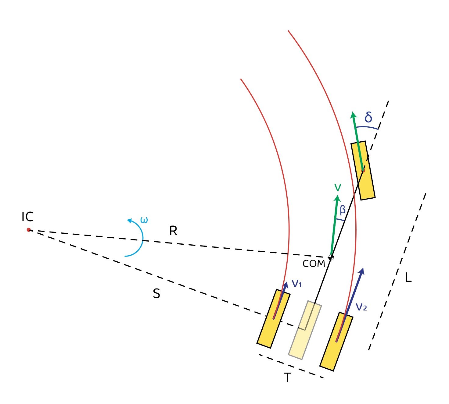
The Python simulator for the 4-wheel vehicle relies on the kinematic bicycle-model to simplify the dynamics and motion of the vehicle into 2 inputs: wheel rear-wheel velocity and front-wheel steering angle. While this model is not ideal for accuracy and complex paths, for small speeds and steering angles, there is documented success using this model to model and predict behavior of 4-wheeled vehicles, despite simplifying the vehicle to only have 2 wheels and neglecting any wheel slip.
pure-pursuit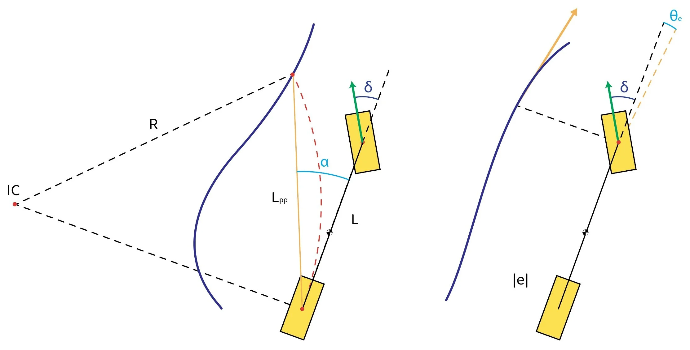
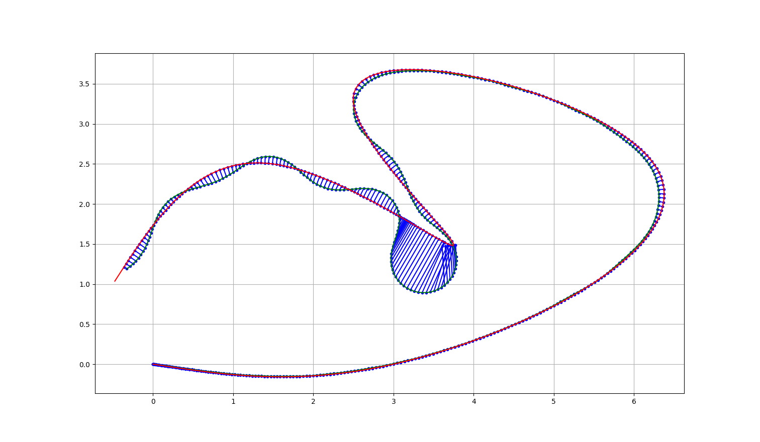
StanleyThe course used to compare the path-following controllers was made using cubic splines to achieve varied curvatures in order to create a path that tested the algorithms with both straightaways and tight hairpins corners. The course was also planned around the available lab space in the building equipped with a ViCon system that another team with the same vehicle used for localization with their control algorithms.
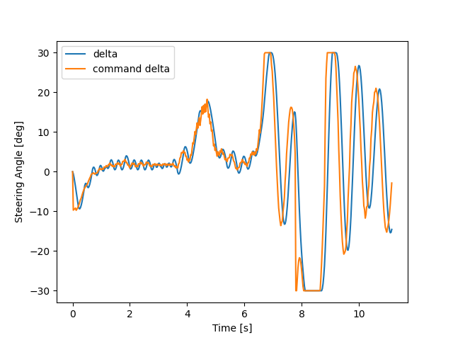
After accounting for the transient behavior of the PID motor position controller implemented on the steering motor on the vehicle, the simulation indicated that the position controllers needed to be retuned. Both controllers, but especially the pure-pursuit controller deviated from the course dramatically when the motor behavior was accounted for. This was fixed by increasing look-ahead distance and lowering the gain of the steering error factor.
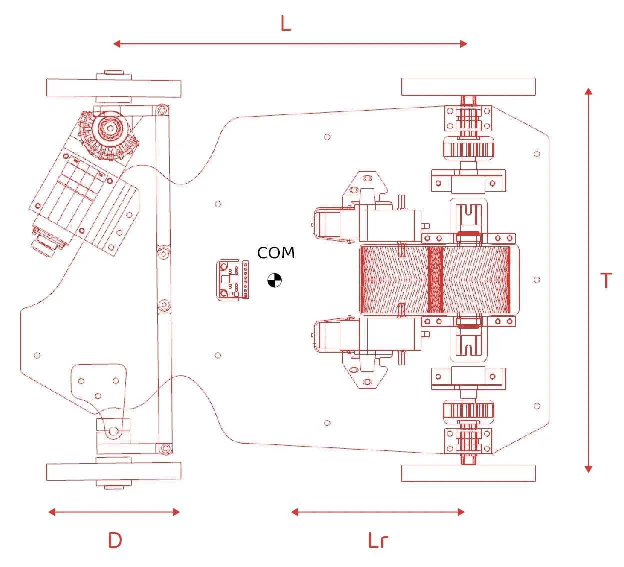
Once the controllers were tuned in simulation, they were implemented on the physical vehicle. The steering and drive systems were actuated by geared brushed DC motors, 1 for steering and 2 used for driving the vehicle. The chassis of the vehicle was lasercut from plastic and most other drive and steering components were 3D-printed. The rear differential was 3D printed inside of a larger drive gear. Encoders were used for feedback control of the steering motor and both of the individual rear wheel positions.
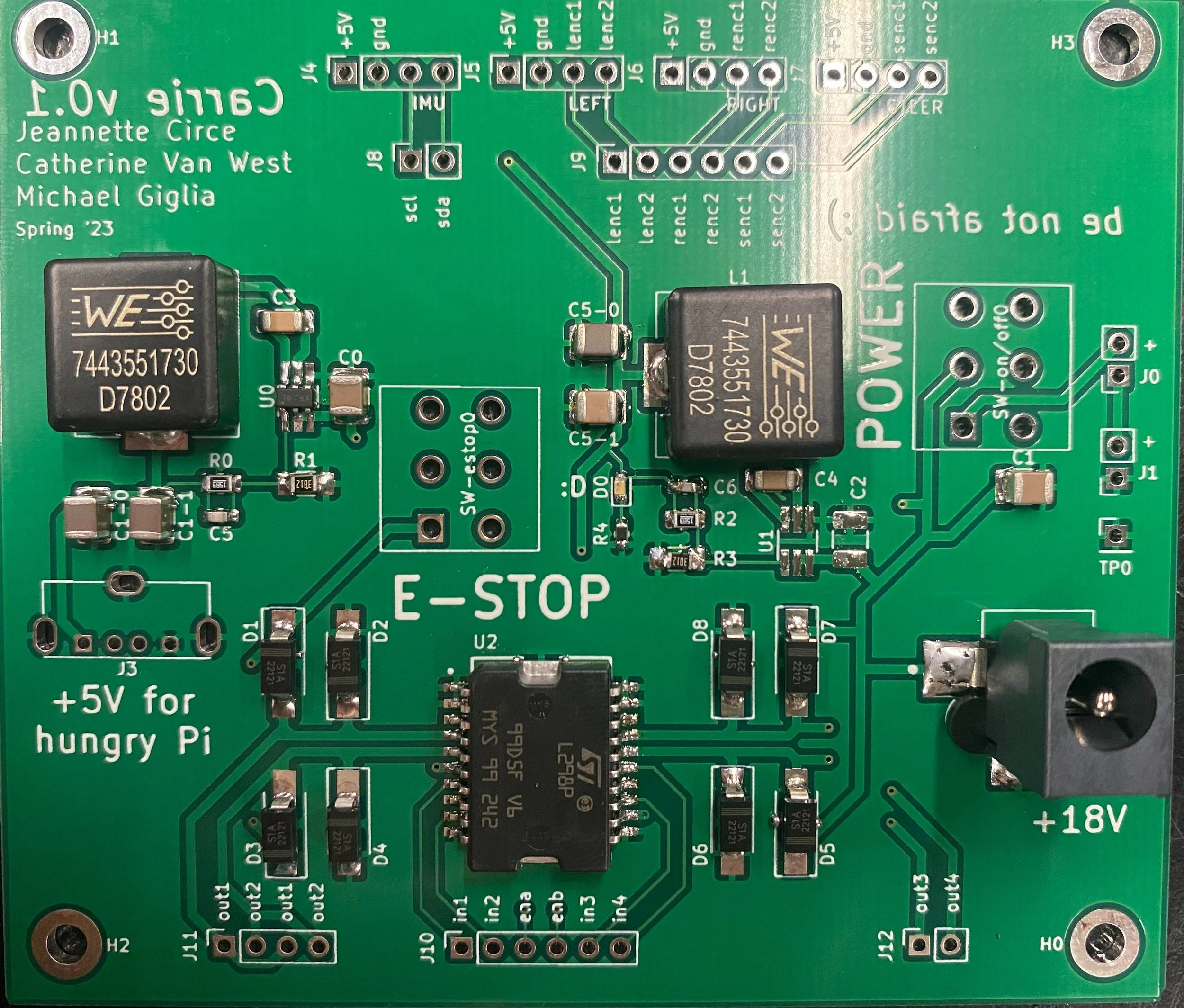
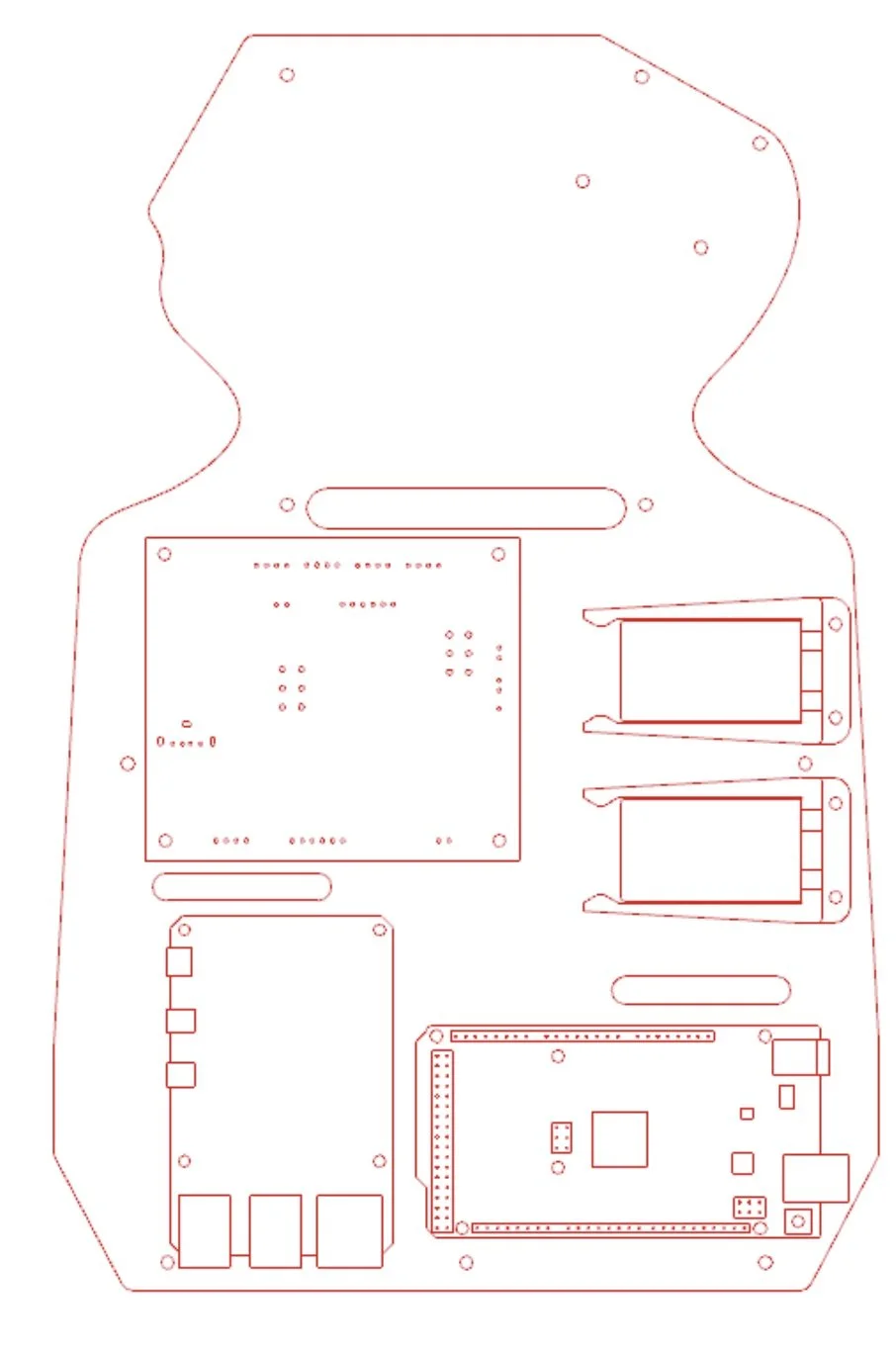
The vehicle was controlled with a Raspberry Pi and Arduino MEGA. The Raspberry Pi used the vehicle state and computed the path-following steering angle and speed. These commands were sent to the Arduino via Serial Communication Protocol. The Arduino then controlled the steering and drive motors with PID controllers with PWM signals sent to an L298 chip. All of the sensors, power management, and motor drivers were on an external board designed by another group of students and lab technicians. This board was assembled by hand and solder-paste and soldered with an oven. The initial plan was to power the car with two 9V batteries, however, the current draw of the motor required the car to be tethered by a power cord to run for extended time periods during extensive testing.

More details on the simulator setup and results, controller tuning, and vehicle characteristics are included in the final paper here.
The Python simulator code is also available on github.
For EE-421 (Advanced Controls), a simulation framework for comparing the performance of various path-following control algorithms for 4-wheel vehicles was programmed in Python and eventually tested on a physical vehicle. Specifically, the simulation utilizes the bicycle model and a steering PID-controller to model the behavior of the “Carrie” car, designed by students and lab technicians at the Cooper Union, when controlled by pure-pursuit and Stanley geometric controllers.
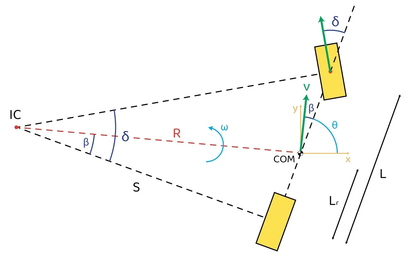
Kinematic Bicycle ModelThe two geometric controllers that were compared to a model-predictive controller (MPC) are pure-pursuit and Stanley. Pure-pursuit calculated the desired steering angle based on a lookahead distance that sees a forward point on the planned path and the angle error between that point and the vehicle’s heading. The Stanley controller uses the cross-track error between the planned path and the front-wheel position of the vehicle and the difference in vehicle heading and nearest point tangency.


Being a kinematic model, the accuracy of the bicycle model heavily relies on using the correct geometry vehicle. To take the accuracy of the simulation one step further, the transient behavior of the steering motor of the vehicle was characterized and also implemented into the simulation to make tuning the control algorithms in simulation more reliable.
pure-pursuitStanley
To quantify the performance of different path following controllers, a number of factors were considered. Depending on the priority of the application of the vehicle, someone might want to prioritize path completion time or trajectory accuracy. For this reason the 3 results used for comparison were run-time, maximum path-trajectory deviation, and total deviation. The better control algorithm would reduce all of these results. However, some controllers compromised deviation from the path to yield a faster run-time, and vice versa.
Because the encoder used in the steering motor was a relative encoder and did not have absolute positioning, when the vehicle was first powered up, it was unaware of its starting position. Therefore an automated calibration technique needed to be implemented to zero the motor to find the position with the front wheels parallel to the vehicle heading. The calibration technique that was successfully implemented on the vehicle used the two encoders on the rear-wheels and the measured speed differential, along with the geometry of the vehicle, to estimate the steering state of the motor and correct it based on the estimate.
When it came time to implement the geometric controllers on the vehicle, the Arduino/Pi needed to rely on some method of localization to determine the current position state of the vehicle with respect to the desired trajectory path. While another group used a ViCon system to get realtime external updates of the vehicle position, my goal was to attempt to use dead-reckoning to estimate the vehicle position. However, due to the low-resolution of the drive motor encoders and the low vehicle speed, accurately measuring vehicle speed and position made it impossible to get a reliable position update. A higher resolution sensor, much larger course, or external gearing of the encoder could result in better speed and position updates. Nevertheless, the group using the ViCon system was successfully able to implement a similar control algorithm on the same vehicle.