Wind Turbine Tower Simulation
The design and simulations were split into 3 main sections: the tower, the baseplate, the cable attachments. Before designing, the forces acting on the tower needed to be calculated based on the nacelle weight and its operating frequency and the shape of the tower with the expected wind conditions. After the forces and moments were calculated, the shape of the tower was finalized and simulations were run to verify it met the required specifications.
Displacement
Thermal Expansion
Natural Frequency
Buckling Analysis
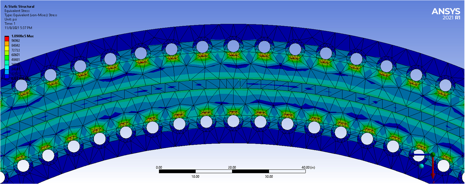
After looking at the reaction forces at the base of the tower under different loading conditions and modes of failure, the design for the baseplate was made. Specifically, the cross-section and number of mounting points around the base needed to be calculated such that the mounting hardware would not fail in tension or shear. The design uses 240 bolts of 3” diameter with 4” washers arranged inside and outside of the tower to prevent it from tipping and shifting. Thermal expansion simulations indicated that the bolt holes should be oversized to 3.375” to prevent the expansion and compression of the tower from shearing the bolts. Simulations were also run to verify that the stress in the baseplate at the point of maximum tension did not exceed the strength of the material


Free Body diagramFor ME-408 (intro to FEA), the group midterm project was to design and run simulations for the tower of a 500' wind turbine that supports the nacelle under various loading conditions. Our group designed a tapered cylinder tower with three steel cable supports. The tower needed to support the weight of the nacelle and blades, the wind acting on the tower and the blades, and weight of the tower itself. The goal of the design was to prevent the top of the tower from deflecting by more than 12" under normal wind conditions and 16" under extreme wind conditions. The tower also had to be designed with a natural frequency outside of the operating range of the spinning blades to allow for safe shutdown in the event that one of the blades brakes or completely falls off. The factor of safety for the tower buckling also had to exceed 8 under any of the different loading conditions.

Simulation results of the tower under extreme wind (125 mph) conditions showed the max deflection of the top tower is 9.6" while hand calculations predicted 14.8". Both are below the specified maximum of 12". The Eigen-Buckling analysis computed a factor of safety of the tower from buckling of 16.2, above the specified minimum FOS of 8. The modal analysis of the tower structure computed a minimum modal frequency of 1.45 Hz, higher than the operating range of the tower's nacelle blades at 12-15 rpm. The largest thermal deformation experienced by the tower between an operating range of -10˚F to 130˚F is 3.5" at the colder temperature.


The third round of simulations were to design and verify the cable mount design that attached to the tower. The cable used was a 3” diameter steel 16x9 Seale pattern with well-documented material properties. Previous simulations had already verified that the tower and cable would not experience excess stress at the mounting point. However, these simulations at the mounting hole verified that the attachment would not fail and detach from the tower.
For more details on the loading conditions and various simulation results, the final report is viewable here.